Typical problems and solutions concerning the M20 power supply
The Olivetti M20 power supply unit is a typical switching power supply. This component is the first one to test in the case of system failure, as it is one of the most solicited part of the whole system.BE CAREFUL, anyway: those circuits have BIG capacitors charged up to 350V, which can store enough energy to seriously hurt you, even when the unit is disconnected from mains!
Symptoms:
The M20 does not start the diagnostic sequence. When powered up, the power on led blinks, the buzzer beeps and then all remains in a quiescent state, with a low low volume continuous beeeeeeeeep.The voltage on the 5V, 12V and -12V lines is correct for several tenths of second after the power up, but then drops to 1/3 or 1/4 of the nominal value.
Other symptoms can be that the computer does not reset correctly. The ON led is on, but the buzzer beeps continuously and the disc drives moves randomly making noise. The voltage are below their nominal value.
Possible solution:
 Avoid to keep the computer switched on continuously. Try to disconnect the video,
the disk drives and every expansion card to see if the voltages remain constant.
There can be a problem in the power supply.
Verify every soldering in the power supply unit to see if it is in good condition.
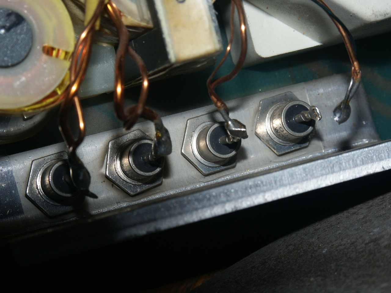
Pull gently every wire that connects the transformer to the four Schottky
diodes mounted on the heat dissipator. If only 2 or 3 diodes are connected, the power supply can not give enough current to the M20 motherboard, but the voltages appear to be correct if tested with a small charge.
Avoid to keep the computer switched on continuously. Try to disconnect the video,
the disk drives and every expansion card to see if the voltages remain constant.
There can be a problem in the power supply.
Verify every soldering in the power supply unit to see if it is in good condition.
Pull gently every wire that connects the transformer to the four Schottky
diodes mounted on the heat dissipator. If only 2 or 3 diodes are connected, the power supply can not give enough current to the M20 motherboard, but the voltages appear to be correct if tested with a small charge.
Symptoms:
Switching on the M20 nothing happened. Only the fan was blowing. Removing the case I could hear clicking noise from the PS. This indicates that the PS wants to start, but a protection circuit comes up to stop it. This happened a few times per second.
Possible solution:
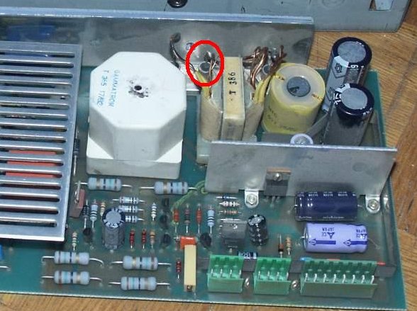
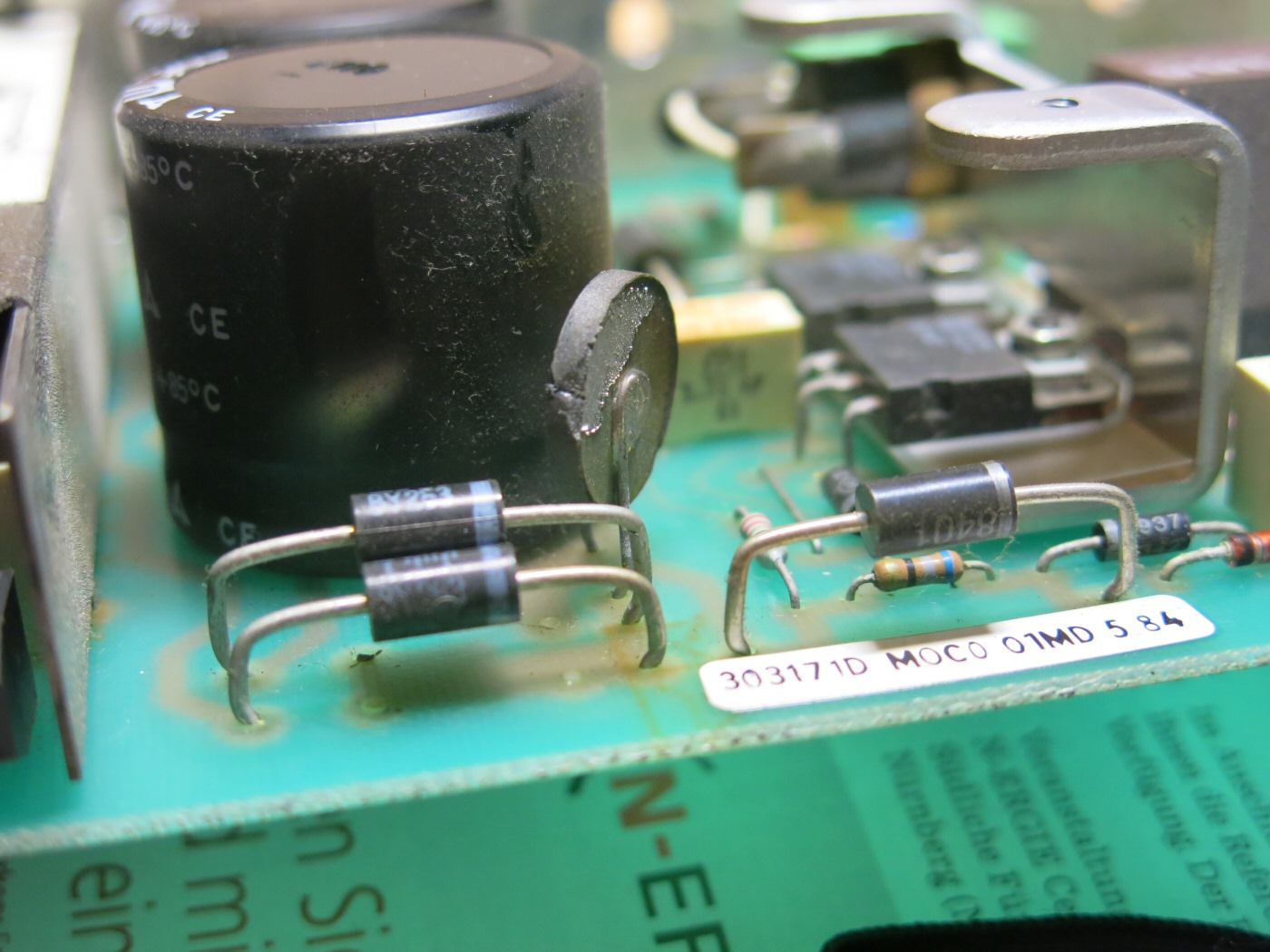
I've measured the secondary part and found a shortcut on the 12V line inside the PS. A defect power diode behind the transformer produced this shortcut (circled in red in the picture at the right).
I could not find the same diode new, so I have taken a double diode from a
newer PC power supply.

Decidedly, you should check those Schottky diodes if you experience problems with your power supply unit!
Replacing the Power Supply
Sometimes, the power supply is just dead. You can probably try to repair it, but you must have the skills, the time and at least an oscilloscope to do it. As part of the circuit is connected directly to the mains, you should know VERY well what you are doing.
 Do not even think to find now an original Olivetti power supply for your M20, if you are very lucky, you can find a broken M20 and you can reuse its power supply.
Anyway, the M20 circuitry requires rather standard voltages: +5V, +12V, -12V, which can be obtained from a standard PC power supply. The problem is that the shape of the Olivetti power supply unit is quite different from the average PC power supplies' one.
Do not even think to find now an original Olivetti power supply for your M20, if you are very lucky, you can find a broken M20 and you can reuse its power supply.
Anyway, the M20 circuitry requires rather standard voltages: +5V, +12V, -12V, which can be obtained from a standard PC power supply. The problem is that the shape of the Olivetti power supply unit is quite different from the average PC power supplies' one.
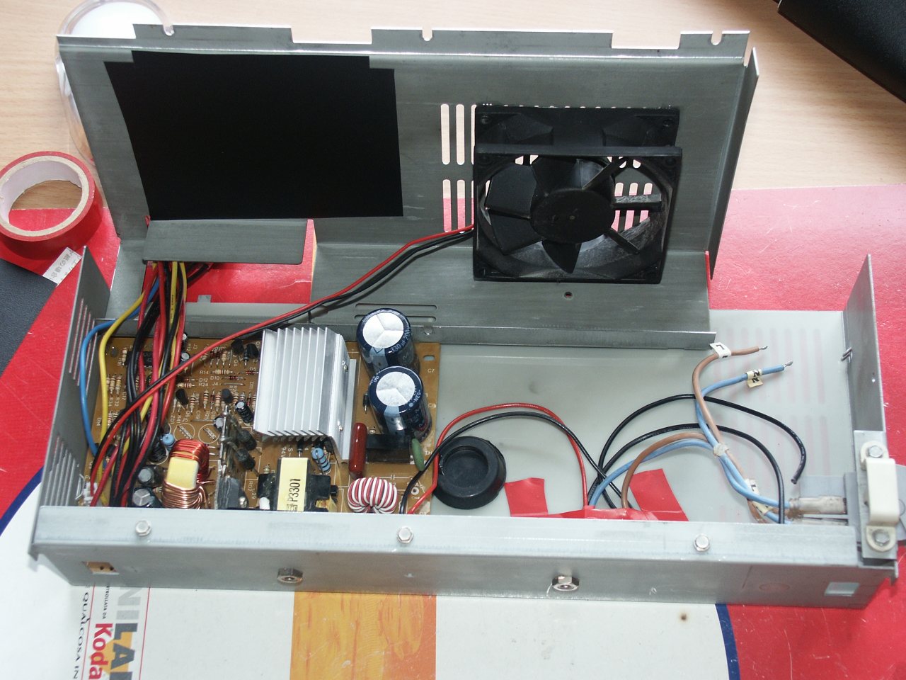
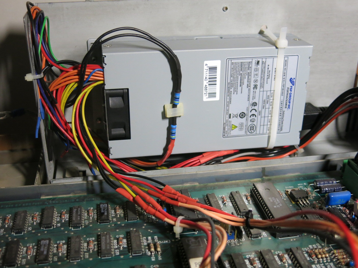
You can think of replacing the circuit inside the box and adapting the M20 connectors to the new power supply. In the picture, you can see the new power supply, with its fan. Be careful, as for disk drives the connector is the same, BUT the wiring is different. Also, heat dissipators can be connected to the mains, fix the circuit in the M20 power supply case and avoid them touch the metallic walls.
Herbert's replacement
 To ensure that the year 2016 has a good start for your M20, Herbert Oppmann, from Nürnberg has sent the following paragraphs, describing in great detail how to select a good power supply unit for the M20 and how to use it instead of the original one. The original PSU in Herbert's M20 had a NTC resistor which exploded as shown in the picture, probably as the result of a more serious problem (a short in the switching transistor?)
The advantage of Herbert's procedure is that he was able to find a suitable power supply unit which does not need to be disassembled to be installed inside the original M20 power supply case!
To ensure that the year 2016 has a good start for your M20, Herbert Oppmann, from Nürnberg has sent the following paragraphs, describing in great detail how to select a good power supply unit for the M20 and how to use it instead of the original one. The original PSU in Herbert's M20 had a NTC resistor which exploded as shown in the picture, probably as the result of a more serious problem (a short in the switching transistor?)
The advantage of Herbert's procedure is that he was able to find a suitable power supply unit which does not need to be disassembled to be installed inside the original M20 power supply case!
1. Removing the original power supply
- Make sure the power plug is removed from the outlet.
- Remove the top of the encasing of the M20.
- Remove the keyboard.
- Unplug the floppy disk and mainboard power plugs from the power supply.
- Remove the floppy disks.
Open the power supply case. It consists of two sheets of metal. A left part, which forms the front, back, left and lower walls, and a right part, which forms the top and right walls. Remove (I think) three small screws. One is on the top left, and two are on the bottom right side. The latter ones are a bit tricky to unscrew. They have a hexagonal head, so you can use a small open-end wrench for this.
Remove the right metal sheet.
Inside, on the bottom, is a metal heat dissipator. Two bigger screws do not only fasten the dissipator on the encasing of the power supply, but they also fasten the power supply on the lower encasing of the M20. Remove these screws, and slide the power supply to the front. On the back side, there is a terminal where the wires of the power cord, the fan and the mains switch are fastened. Loosen them, and also loosen the strain relief of the mains cord. Now the power supply can be removed.
Remove the PCB from the left metal sheet. You may throw away the PCB and the right metal sheet. But keep the left metal sheet, because it is needed to mount the new power supply. It also holds the power switch and the strain relief of the mains cord, which we can re-use.
2. Selecting a new power supply
Now check your power needs. According to the Olivetti M20 hardware manual, page 2-67, the M20 power supply does:
- +5 V max. 9.0 A
- +12 V max. 5.6 A
- -12 V max. 0.7 A
But depending on your configuration, you might need a bit less. See Olivetti M20 hardware manual, page 4-1 for the consumption of the individual units. For my M20, this is:
- 5 V: 3.51 A Motherboard + 1.0 A Keyboard + 2 x 0.75 A Disk drive + 0.045 A Memory Board Monochrome = a bit more than 6 A
- 12 V: 0.585 A Motherboard + 2 x 1.15 A / 1.85 A Disk drive + 1.5 A Display + 0.6 A Memory Board Monochrome = a bit more than 6 A
- -12 V: 0.03 A Motherboard + 0.0032 A Memory Board Monochrome = negligible
I found out that the PC power supply in the Mini ITX form factor (150 x 81.5 x 40.5 mm) fits nicely into the place of the M20 power supply. I used the FSP180-50LE 180 W power supply. See attached PDF. It can deliver:
- +3.3 V min. 0.3 A, max. 14 A
- +5 V min. 0.3 A, max. 16 A
- +12 V min. 1.5 A, max. 14 A
- -12 V no min., max 0.5 A
- +5 V standby no min., max. 2 A
We do not need +3.3 V and thus have to use ballast resistors to observe the minimum current. 3.3 V / 0.3 A = 11 ohm. But as both the output voltage and the resistors may have a variance, I used a slightly smaller resistor value to be on the safe side. The dissipation is nominally 3.3 V x 0.3 A = about 1 W, but due to the tolerances and the slightly smaller resistor, the dissipation is slightly above 1 W. Resistors above 1 W were not readily available to me, so I used two 1 W resistors of 4.7 ohm in series.
The other voltages do not need ballast, because the M20 already uses enough current. Even if a plug loosens, nothing bad will happen because this power supply has protective logic which shuts down to a sense mode and returns to normal operation once the conditions are good again.
3. Mounting the new power supply
The orientation of the new power supply was chosen so that the air flow through the power supply is in the same direction as the air flow of the fan of the M20. This orientation is also convenient because the high voltage wires are then very short and straight.
Four holes have to be drilled into the left metal sheet of the original encasing. Two for the attachment bracket on the front, and two for a strap fastener at the back. Do not yet fix the power supply on the left metal sheet, because you won't be able to reach the screws which hold the metal sheet in the lower encasing of the M20!!!
I sacrificed a power cord which has an IEC power connector because I did not want to open the encasing of the new power supply and solder wires on the high voltage side. Cut the power cable at appropriate length, remove overall insulation for ca. 10 cm so the wires can be moved. Remove insulation on individual wires for ca. 6 mm. We now need a crimping tool and two insulated flat plugs. These go to the brown (L = line) and blue (N = neutral) wires. Remember to slide the insulation of the plug to the wire before crimping the plug and then sliding the insulation over the crimped plug. Crimp an eyelet on the yellow/green wire (PE = protective earth). Now do the same with the original mains cord. If you removed the cord completely, please insert it into the lower encasing of the M20 before crimping the plugs.
The main cord plugs go to the mains switch, to the lower contacts, and the cord with the IEC plug goes to the upper contacts of the mains switch. Now the protective earth lines have to be connected with each other and with the left metal sheet. There is a hole in the metal conveniently above the mains switch, where a screw can be used to tie everything together. Unfortunately, the PE wire from the fan is too short, so take a yellow/green wire of appropriate length and crimp eyelets on both ends. High voltage side done!
Now fasten (screw) the left metal sheet into the lower encasing of the M20. Do NOT use the original screws, because these are now too long (the heat dissipator is missing).
Fix the new power supply on the left metal sheet with two screws and the fastener strip.
Look at the lower voltage connectors and make notes which wire color is used on which pin. Most of the times the colors follow the same scheme, but better be sure. Now cut off the low voltage plugs. Not directly behind the plug; keep about 2/3rds of the wire length and remove 1/3rd.
Take the original M20 motherboard and drive power wires and cut off the plugs that were once plugged in the power supply. Also here, do not cut directly after the plug, but also take away of excessive wire length.
For the next step, you now need some helping hands, because you have to solder together several wires. Insulate the soldering connections carefully. I used shrink-down plastic tubing because it is more professional and because I own a regulated hot air blower (don't forget to slide the tube over the wires before soldering!). But insulating tape will also do.
- 3.3 V (usually orange): Connect at least one, better two of them, together with the 3.3 V sense (usually brown) and with one ballast resistor. Connect the other end of the ballast resistor with the next ballast resistor and the other end of this one to at least one, better two, of the Ground wires (usually black).
- +5 V: Connect +5 V (usually red) to the M20's red +5V lines. Typically connect two red lines from the power supply with one red line on the M20 side.
- +12 V: [Attention: The wiring standard allows for separate 12 V outputs defined as +12V1 and +12V2. Study the description of the power supply, whether these are internally connected or are really separate outputs. If separate or if you are unsure, do not connect a +12V1 wire together with a +12V2 wire.] Connect +12 V (usually yellow) to the M20's orange / pink +12 V lines. Typically connect two yellow lines from the power supply with one orange/pink line on the M20 side.
- -12V: Connect -12 V (usually blue) to the M20's grey -12 V line.
- Connect the "Power on" wire (usually green) to Ground (usually black). Otherwise the power supply will not start.
- Ground: Connect ground (usually black) to the M20's black ground lines on the motherboard and disk cords. Typically connect two black lines from the power supply with one black line on the M20 side.
Isolate the ends of all unused wires of the power supply, especially the +5V standby wire (usually purple) and the "Power good" wire (usually grey).
Mount the ballast resistors somewhere (I placed them on the right side of the power supply, where they are in the air flow of the M20's fan). Slide the unused wires below the power supply. Use straps to keep the individual wires of a power cord together.
Done!
Chris Carter's experience repairing an M20 power supply
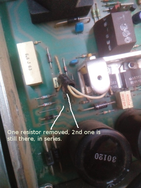 Recently one of the M20s PSU went faulty and my brother managed to fix it, as he has
worked on switch mode supplies a lot in the past... The problem was that 2 resistors,
which are in series and are acting a `kickstarter` for the oscillator, were dead - apparently this was
a common cause of dead switch mode PSUs.
Recently one of the M20s PSU went faulty and my brother managed to fix it, as he has
worked on switch mode supplies a lot in the past... The problem was that 2 resistors,
which are in series and are acting a `kickstarter` for the oscillator, were dead - apparently this was
a common cause of dead switch mode PSUs.
One thing interesting was that we found that the PSU needed a load (we re-attached just one floppy drive) to get the right otuput voltages... without the load you get very low readings - which may be the symptom described in your Power Supply notes.
Page log
- Feb. 5, 2020 - added Chris Carter's notes.
- Jan. 10, 2016 - inclusion of Herbert's procedure.
- Jun. 13, 2008 - general review.
- Aug. 30, 2005 - original version of the page.
Olivetti is a registered trademark of Telecom Italia. This site is not related to Olivetti nor to Telecom Italia. The material presented is meant for personal use only and is shared in a "fair use" spirit. If you own the copyright of some of the stuff presented here and you think it should be removed, please contact the webmaster.