Connecting a hard disk to the M20
by Dwight ElveyI was intrigued by the thought of adding a hard disk to my M20. A fellow M20 (Andreas) owner was attempting to replacing the failed drive in his M20. He noted that the MFM ST251 had the same number of heads as the original but had about 4 times as many cylinders. The rotational speed was also the same as the original 11 Meg Olivetti hard drive. This lead me to think it might be practical to add a hard drive to my M20 as well. He had connected the ST251 to his machine but it was failing to format correctly. I decided that it could be done.
 I've spent some time analyzing the controller shown in the
hardware manual schematics. I'd described this to another
friend (Tony) and he said that it seemed to be a copy of
the WD1000 controller. I located a schematic and manual on Al
Kossow's ftp site for the WD1000. The Olivetti did indeed seem to
be a WD1000. It didn't have some circuits that were not use, such
as the DMA and interrupt circuits but it was otherwise the same.
I started a search for a compatible controller. Tony had also
mentioned that the early Tandy TRS80 5 Meg drives came with
a controller that was similar to the WD1000 in the same
enclosure. He also stated that the later drive systems used
a WD1002 controller. More on that later.
I've spent some time analyzing the controller shown in the
hardware manual schematics. I'd described this to another
friend (Tony) and he said that it seemed to be a copy of
the WD1000 controller. I located a schematic and manual on Al
Kossow's ftp site for the WD1000. The Olivetti did indeed seem to
be a WD1000. It didn't have some circuits that were not use, such
as the DMA and interrupt circuits but it was otherwise the same.
I started a search for a compatible controller. Tony had also
mentioned that the early Tandy TRS80 5 Meg drives came with
a controller that was similar to the WD1000 in the same
enclosure. He also stated that the later drive systems used
a WD1002 controller. More on that later.
I watched eBay until I found a 5 Meg drive for sale. I bid
on it and won the bid. I'd located a manual with schematics
for this controller as well, on the web. With this I began
to bring the pieces together to add the hard drive.
The Olivetti had a small interface card on the M20's
expansion bus to connect to the controller. I needed to
create this first and match it to the TRS80 controller.
The first problem was locating a suitable proto typing
board with the right spacing and number of pins.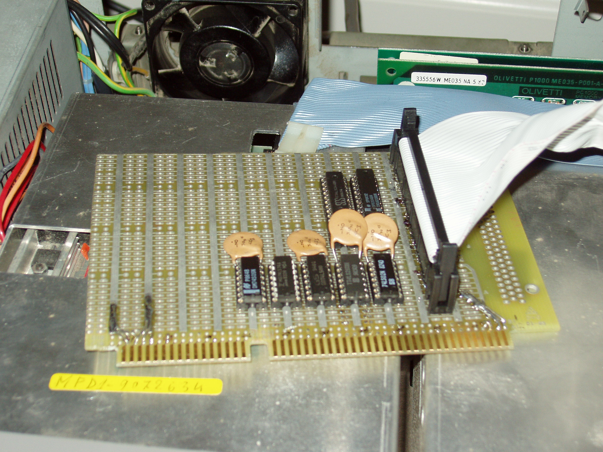 I found
that if I used a cut down 16 bit ISA connector, with the
notch located in the right place, I could get all the
signals I needed for the interface card. The notch is
located such that it is where I don't need any connections.
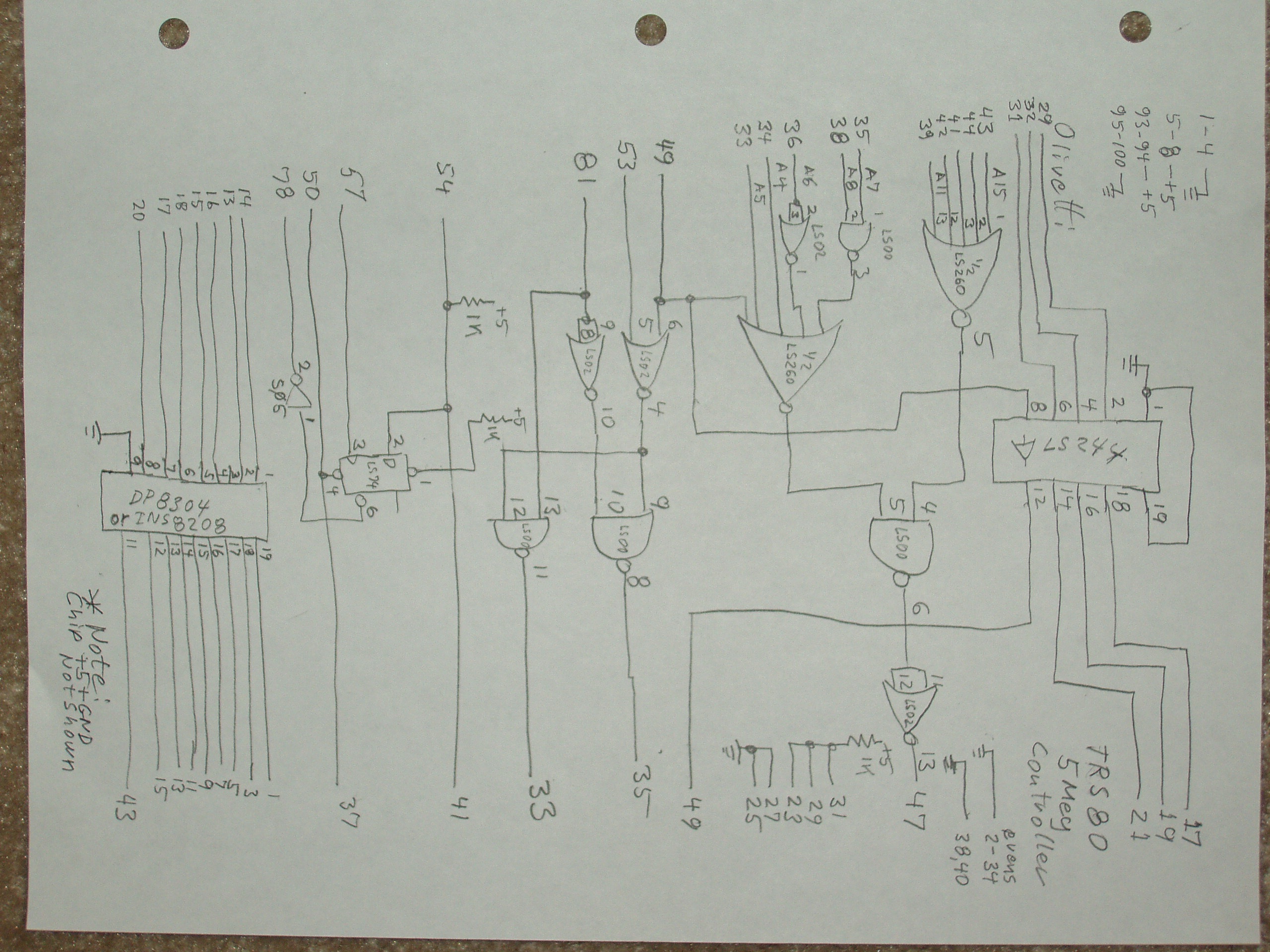
I started analyzing the original interface and looked at
what was different on the Tandy controller. The Olivetti
card did the port address decoding, read and write strobe
separation and a wait state latch. The Tandy controller
had a built in address decoder. I arranged things so
that the two matched up. I didn't optimize the address
decoding because I originally was expecting to connect
to a WD1000. This meant that I just tied several of
the Tandy's address lines and only used a few as selects.
I found
that if I used a cut down 16 bit ISA connector, with the
notch located in the right place, I could get all the
signals I needed for the interface card. The notch is
located such that it is where I don't need any connections.
I started analyzing the original interface and looked at
what was different on the Tandy controller. The Olivetti
card did the port address decoding, read and write strobe
separation and a wait state latch. The Tandy controller
had a built in address decoder. I arranged things so
that the two matched up. I didn't optimize the address
decoding because I originally was expecting to connect
to a WD1000. This meant that I just tied several of
the Tandy's address lines and only used a few as selects.
I connected the interface and drive to my M20 and found the M20 failed to boot. After locating several wiring errors on my interface card, it still was loading something down. Looking at the Tandy, I found that they had put some bus termination resistors on I/O's. I found that I needed to add some buffering to connect to the M20. I added this and was able to boot the M20 to floppy. Now the next step was to try to format the drive. I tried the vf command but it failed to create the needed format. There were several problems. I realized I'd need to track down multiple issues.
I'd gotten a disk image from Chris' ftp with the assembler
and linker. This allowed me to write some assembly code
to start to check out the controller. The floppy disk also
had a debugger (pdebug).
With the debugger I confirmed that I'd properly connected
the bus to the controller. All of the WD1000 registers
were there and properly mapped to the correct locations
in the M20 I/O space.
 I wrote some simple code to try to format track 0, head 0.
When I tried this, I got a "ID not found" error. This meant
that it was not formatting correctly. I also recall that
when I first used the vf command, it started OK and stepped
through the tracks. Subsequent attemps to use the vf
failed right away with the message that it couldn't read
the bad sector map. This indicated that the controller
did read the disk that was formatted for use with DOS
but the format was destroyed by the controller when the
format was attempted.
I wrote some simple code to try to format track 0, head 0.
When I tried this, I got a "ID not found" error. This meant
that it was not formatting correctly. I also recall that
when I first used the vf command, it started OK and stepped
through the tracks. Subsequent attemps to use the vf
failed right away with the message that it couldn't read
the bad sector map. This indicated that the controller
did read the disk that was formatted for use with DOS
but the format was destroyed by the controller when the
format was attempted.
There was still something wrong in the controller. I
my oscilloscope out and started tracking the write data
signals. These got lost right at the final mux that
selects the early,normal and late data. Tracking what
was causing the problems lead to a signal from Pin 5
of the data connector. It seems that the Tandy drive
had some type of write enable signal connected to this
pin while the ST251 had nothing attached. I tied this
line and continued to play with getting things going.
As I was checking things out, I found that if I wrote
a SEEK or RESTORE command to the hard drive, I could
successfully format and right files. If I reset the
M20 and booted from the floppy again, it would fail.
I started to scan the code in the ROM (1.0 bootloader)
and the floppy disk (2.0F). I located the routines
that effect the drive on the floppy. I later learned
that the newer systems bootloader ROM had the hard
drive code built in. I had created images of my boot
disk and found the places where the step rate and the
precomp values were set. I edited these on my PC using
xtree's hex edit. I then create a new boot floppy
with my WRM20 program.
I was then able to create a good disk format and read/
write files to the hard drive.
 Now on to Andreas' problems. We had numerous problems.
First he was using an original Olivetti controller that
turned out to have a defective write. The ST251 that he had
had serious blocks of bad tracks. He eventually located
a NEC drive and another Olivetti drive to play with.
Working with a borrowed controller, we eventually got
him running as well. One major difference was that
his bootloader ROMs had the built in hard drive driver
code in them. These interfered with experiments at
several stages. I finally figured out how to edit
the ROMs and update the checksums (thanks to Chris'
ROM.s code). With good ROM code progress was made
on Adreas' machine as well.
Now on to Andreas' problems. We had numerous problems.
First he was using an original Olivetti controller that
turned out to have a defective write. The ST251 that he had
had serious blocks of bad tracks. He eventually located
a NEC drive and another Olivetti drive to play with.
Working with a borrowed controller, we eventually got
him running as well. One major difference was that
his bootloader ROMs had the built in hard drive driver
code in them. These interfered with experiments at
several stages. I finally figured out how to edit
the ROMs and update the checksums (thanks to Chris'
ROM.s code). With good ROM code progress was made
on Adreas' machine as well.
At several points along the way, we destroyed the formatting on the disk enough so that the PCOS vformat instruction failed to work. This took quite a bit of work to bring the drives back to a state that we were able to run vformat with the right parameters to handle the non-Olivetti drives. For this, I wrote a program that would do a low level format regardless. It seems that the vf command needs some tracks to be readable.
I wrote several programs using the PCOS assembler. I would run these programs from the floppy. I found it easier to use an editor that I was familiar with so I did all the editing on my PC.
I wrote a simple translator program to convert DOS text files into PCOS text files. PCOS uses 1Eh for end of line instead of the DOS 0Ah,0Dh. I wrote another to go from PCOS to DOS as well. This was handy to look at listing files while using pdebug on the M20.
I transfered files between the PC and M20 using two programs found on the 2.0F PCOS disk. These two files (dos2pcos and pcos2dos) allow one to move a file on a floppy formatted as a 320K DOS disk. (getting a 320K instead of a 360K from the DOS format instruction is tricky but can be done).
Programs I've written:
| hf.cmd | Does a low level format and writes to each sector to clear errors that block the PCOS vformat command from working. |
| rsect.cmd | Reads a sector specified as Cyl,Hd,Sect. As an example: rsect 0,0,0 will read the cylinder 0, head 0 and sector 0 and display in hex on the video. |
| of.cmd | The same as hf.cmd but is used for the Olivetti drives and with Olivetti parameters. |
These commands are all intended to be used with the Bootloader 1.0 and the modified PCOS 2.0f or 2.0h floppies. These are to be used with hard drives that don't need procomp and do the automatic step timing (most newer drives are of this type). They can be used with newer Bootloader ROMs but the ROMs need to be modified, similar to the floppies. Once one gets things started and can do a vformat, one needs to run vverify. This program has options to enter bad sector information as well as a test for bad sectors. If running the destructive test, one will need to rerun vformat.
Modifications to PC prototyping board:
I used a Vector brand wire wrap proto typing card.I used a sharp hacksaw blade to trim it as follows:
- From the back end of the board: 6.25 inches
- From the bottom of the connector to the top: 4.125 inches
- Remove the last 2 edge pins of the C/D connector by cutting down between pins 17 and 18. I then used a file to fine adjust so that it would go into the Olivetti bus connector. I peeled any remains of pin 17 off the board.
- Cut and modify the power and grounds to match the Olivetti bus connector.
- Note that the connecter B row is the Olivetti odd pins and the A row are the even pins.
- Make sure things clear the fan if intending to use the last socket.
Modifications to software:
Modifying the floppy images is relatively easy. There are no checksums to worry about. Scan the floppy with a text editor, find the following and make changes. The letter n is a register number so far I've seen n=0 or n=8. Your version may be different so I left it undefined.
Was: Cn 20 3A n6 01 C3Change to:
Cn 32 3A n6 01 C3 (32 would be sector 200, just someplace beyond 180 so it never uses precomp).
Was: Cn 14 3A n6 01 CF
Change to:
Cn 10 3A n6 01 CF (Auto step enabled)
If you are editing an EPROM instead of a floppy, you need to modify the last byte by XORing that value with 16h. Also note that the EPROMs contain odd addresses in one and even addresses in the other. The above edits are easiest done on an interleaved image of both EPROMs.
Modifications needed to Tandy Controller Board:

- Signal pin cut at U47-19. Line to other chips tied to plup.
- Signal at J1-5 tied to ground.
Other controller choices:
It is believed that one can use a hard drive controller
from an XT, using the Olivetti interface card as
can be copied from the schematic in the hardware manual.
The only thing to watch out for is that the controller
connectors address lines A0 to A2 are incorrectly
connected in the schematic. These lines should be
connected controller side A0, A1 and A2 to the M20
bus side A1, A2 and A3.
There is only a small amount of circuitry on the interface
card.
Drive Parameters:
| parameter | Olivetti | ST251 |
|---|---|---|
| steprate | 2.0 ms | 8ms or Auto |
| Precomp | 128 | no Precomp |
| heads | 6 | 6 |
| RPM | 3600 | 3600 |
| Cyls | 180 | 820 |
(June 19, 2006)
Addendum February 18, 2019
I had a recent request for the low level words that I used to do a low level format before I used the vf command to format the hard drive. I don't have the *.cmd files but I do have the source code that can be downloaded here.
These files are in DOS format. That means CR LF (0Dh 0Ah) would need to be converted to a single character 1EH (as I recall) for PCOS to see it as an enter. It should be easy to write a basic or other language program to fix these for PCOS.
These could be copied over using the method I described, on the web page, with a 320K DOS format disk or worst case, just entered in the PCOS editor, by hand. They are not that big. The files are labeled as *.TXT but should be *.S for PCOS.
They can then be assembled and linked with the PCOS assembler. Assemble the source files to *.o files. When linked, output to *.CMD files
The files are:
- CLRS0.S Used to clear the data on the first sector when used on some other OS. PCOS expects to see a table of bad tracks on the first sector of the disk. It will fail to format if it can't figure out that first sector because of some other data there.
- HDFORMAT.S Assumes you have a hard disk that need auto-step instead of a fixed track step. Does a low level format of the entire disk (11Meg as seen by PCOS). The disk must still have enough heads, rotation rate and track to match the Olivetti disk. I used a ST251 as I recall.
- OFORMAT.S The same as HDFORMAT but uses the fixed steps of the original Olivetti 11M hard disk.
- RDSECT.S Reads the specified sector of the disk and displays in hex. Useful for analyzing the disk. I'd need to look at the source file to tell which parameters to type in which order. It was head#, track#, Sect#, as I recall.
- PARK.S Does a park of the head. A useful thing to do before turning the power off. Some say that it helps protect the disk. These older drive would just land the heads where ever they were, unlike the newer disk that lift the heads off the disk on power down.
Page log
- Feb. 11, 2024 - Added this log.
- Feb. 18, 2019 - Updated the HD programs, added instructions for the low-level format.
- Jun. 19, 2006 - Original version of the page.
Olivetti is a registered trademark of Telecom Italia. This site is not related to Olivetti nor to Telecom Italia. The material presented is meant for personal use only and is shared in a "fair use" spirit. If you own the copyright of some of the stuff presented here and you think it should be removed, please contact the webmaster.