Configure the mainboard for 128KiB expansion cards
by Davide Bucci, Dwight K. Elvey, Andreas Senk and Benjamin EberhardtIntroduction
 In the case you have modified your 32KiB memory expansions to accept 6164 chips or if you have built a memory expansion of your own, you will need to configurate the M20 motherboard in order to decode 128KiB for each expansion slot. The M20 BIOS is able to recognize the number of expansion cards installed, but not their size, which is specified with the jumper settings.
The settings in this page are useful for 128KiB expansions.
In the case you have modified your 32KiB memory expansions to accept 6164 chips or if you have built a memory expansion of your own, you will need to configurate the M20 motherboard in order to decode 128KiB for each expansion slot. The M20 BIOS is able to recognize the number of expansion cards installed, but not their size, which is specified with the jumper settings.
The settings in this page are useful for 128KiB expansions.
The first thing you need to do is to recognize the motherboard revision you have. We are currently aware of two main motherboard types, as cited in the "Olivetti M20 installazione ed uso" manual. If your motherboard is different from the ones shown here, please contact us!
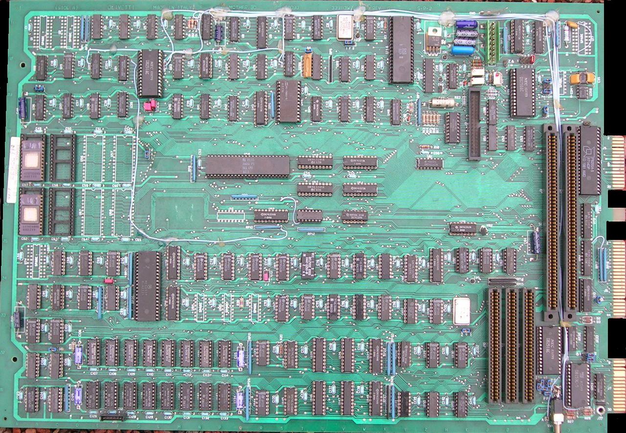
The "D" revision
 The first one is the older "D" revision, with the Z8001 processor placed at the end under the keyboard. This kind of motherboard is also caracterized by four multiplexers IC socketed near the 128KiB ram bank. The description of the function of each jumper is available on this page.
I realize that the L1 DES may have different jumper configuration. but here is what I did on my M20 to reconfigure for the larger RAM expansion cards. First, working with the schematic on Chris' site and making a dump of the address decoder PROM, I figured what jumper configuration would be needed to get things working with the larger RAM cards. I don't recall which jumpers were in there original configuration but here is what I copied from my mother board this morning.
Note: this is an early board and may be a little different on newer boards. Also, if you trace the connections in the schematics or compare to what is in the hardware manual for the address decoder PROM, some lables don't make any sense. I ignored the lables and just configured it to work based on a dump from the PROMs
First the following parts should be socketed. Remove them from the sockets. These are address muxs for the 16K parts:
U62, U63, U64 and U65
Place the mother board such that the keyboard end it towards your right and the power supply is toward you. Just to the left and up a little from U65 is a jumper field with 8 jumper locations place 8 jumpers here (reconnects to 64K muxs). Look to the right of the first RAM expansion socket. There should be a jumper labled 32K/128K. Put a jumper on the 32K position (I suspect the silk screen was wrong).
Look to below and a little to the left of the 8 jumers you installed and you should see jumper pins labled TSN1/PU. Connect a jumper to PU. Look below U63 and there should be a jumper labled TSN1/TA15. Connect a jumper on TSN1. Look below and to the right. There should be a jumper labled TSN0/TSN2. Jumper TSN2.
Look below the large part below this and there should be a jumper labled (128K-224K)/512K. Jumper the 512K end.
Look to the left and you should see a jumper labled ZA. It should be jumpered at the 2 end. Look a little to the left and down. You should see a strip of jumpers labled VIODA to VIODG. Use only a single jumper on VIODA.
Look to the left about 4 inches (10cm). There should be a jumper field labled T11-N on one end and T11-D on the other. Place a jumper on the T11-D end. Skip one jumper location and place one more jumper. The T11-N end should not have a jumper. This should configure the mother board to except memory expansion cards with 128K instead of the 32K boards.
 You can see here a picture of Dwight's board correctly configured. The resolution should be enough to identify the jumper settings. This is an expanded board, with 384KiB of total memory. The BIOS scans the expansion slots for 128KiB expansions.
 You can see here (for comparison) an unexpanded board. The total memory is 128KiB. In this case, no expansion is addressed.
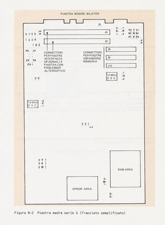
The "G" revision
The G revision is caracterized by a slighlty different parts layout. In particular, the Z8001 microprocessor is in the central area of the board. This motherboard type does not need to disconnect the 32KiB multiplexers and the configuration is done by jumpers only. Here is what Andreas writes about the settings:
 I'm the owner of an Olivetti M20 with board revision : G, and an Olivetti L1 DES with board rev.: D
The L1 DES Board is similar to the board Dwight Elvey shows in his report about modyfying ram expansion cards.
This helped me very much to modify my L1 DES to 512k.
Now, that I could be sure my memorycards have properly been updated I wanted my M20 also to accept 128k memorycards, but this board is completely different in chip layout and jumpers.
It took some time for me to find out how to modify the jumpers to have the full access to 128k instead of 32k expansion cards.
Here is a list of jumpers that have to be changed.
I've also made some photos of the original and the modified settings.
Blue jumpers belongs to other hardware configurations (disk drive type ...)
Jumpers in red are the ones that have to set to accept the expanded memory cards.
 Andreas' motherboard, configured for 128KiB expansions.
Jumpers to be set :
W-1
K-1
V-2
Jumperblock X: 8-1 Jumper set
M-2
JJ : 1-2
 Andreas' motherboard, in the original configuration (at least one 32KiB expansion).
Jumpers original:
W-2
K-2
V-1
Jumperblock X: 8-1 Jumper not set
M-1
JJ : 2-3>
Benjamin Eberhardt has sent in 2024 some pictures of his rev. G board, configured from 32 KB (old) to 128 KB (new) ram expansions. He used bright orange jumpers for the 128 KB configuration. The last picture shows the system equipped with a modern 128 KB expansion made by Salvatore Paxia.


Page Log
- October 14, 2024, Added pictures of the rev. G motherboards and screenshots of the PCOS boot.
- July 27, 2023, Added link to the page about jumper configuration for rev. D motherboards.
- July 1, 2006, First version of the page.
Olivetti is a registered trademark of Telecom Italia. This site is not related to Olivetti nor to Telecom Italia. The material presented is meant for personal use only and is shared in a "fair use" spirit. If you own the copyright of some of the stuff presented here and you think it should be removed, please contact the webmaster.