
Building a 384KiB memory expansion for the M20, part II
By Davide BucciIn the first part of this description, we have seen how two 30 pin SIMMs could be used to make a 128KiB memory expansion for the Olivetti M20. The main idea was that the signals used in the original Olivetti expansion were not so different with those needed in a SIMM. In this part, we will see how to reduce the vasted space in the SIMMs (remember: 128KiB in 2MiB, a 12.5% ratio), using signals taken from the other two memory expansion connectors.
 The more obvious solution was to make three memory expansion, wich could be used in the three memory expansion connectors. I did not like that and, discussing with Dwight K. Elvey, we noticed that the BWMCS1 signal was used to select the expansion on the first connector. Looking at the M20 schematics (Hardware guide, page 7-15), it appears that the data and address lines are common between the three memory connectors and the three memory expansion cards are selected with the corresponding BWMCS signal.
This means that the only signal needed in the two other RAM expansion connectors (apart those used in color expansions) is the BWRMC line.
The more obvious solution was to make three memory expansion, wich could be used in the three memory expansion connectors. I did not like that and, discussing with Dwight K. Elvey, we noticed that the BWMCS1 signal was used to select the expansion on the first connector. Looking at the M20 schematics (Hardware guide, page 7-15), it appears that the data and address lines are common between the three memory connectors and the three memory expansion cards are selected with the corresponding BWMCS signal.
This means that the only signal needed in the two other RAM expansion connectors (apart those used in color expansions) is the BWRMC line.
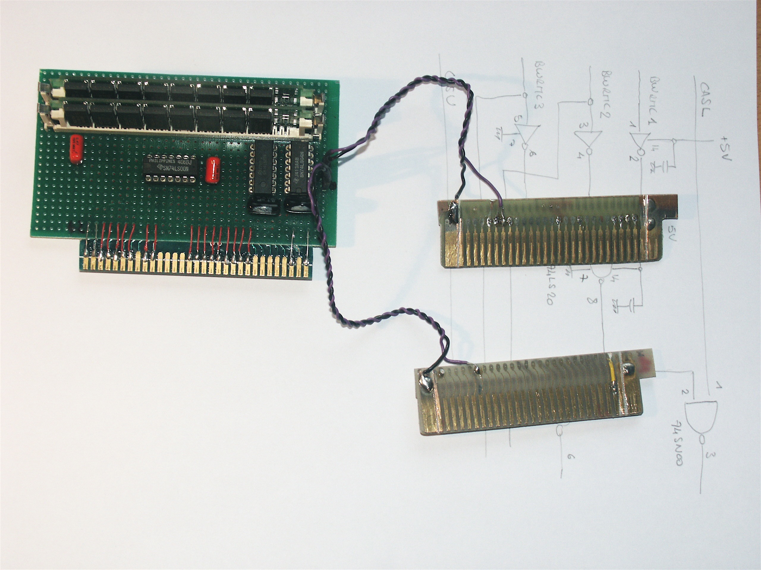
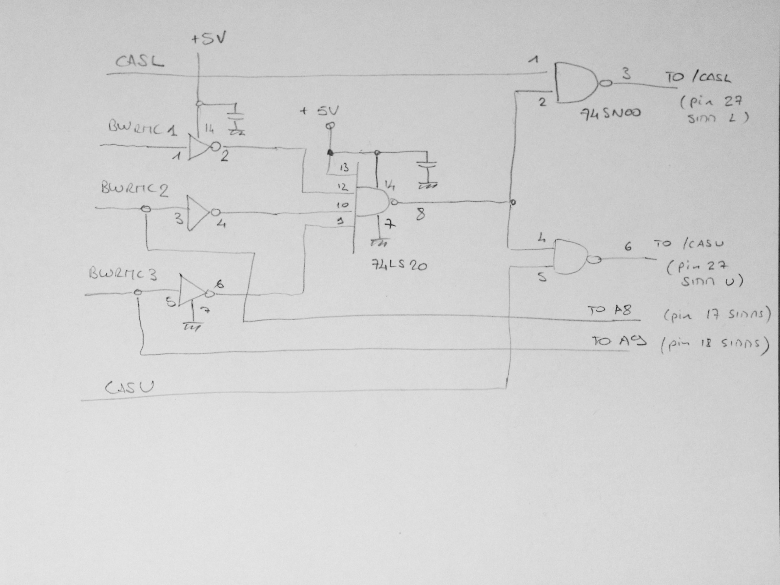 Basing ourself on the schematics of the 128KiB expansion, we need to modify the selection system. The two NAND ports which blocks the RASU and RASL lines if the BWMCS1 is not active must be feed with an AND of the three signals BWMCS1 (pin 46 of the first connector), BWMCS2 (pin 46 of the second connector) and BWMCS3 (pin 46 of the last connector). The BWMCS2 and BWMCS3 signals are used as additional address lines and tied directly to pin 17 and 18 of the two SIMMs.
A suitable part which can be used is a three input OR gate, such as the 74LS54. Since I did not owned that particular one, I used the half of a 74LS04 hex inverter and a 74LS20 quadruple input AND gate. The net result is the OR function (DeMorgan's rule).
Basing ourself on the schematics of the 128KiB expansion, we need to modify the selection system. The two NAND ports which blocks the RASU and RASL lines if the BWMCS1 is not active must be feed with an AND of the three signals BWMCS1 (pin 46 of the first connector), BWMCS2 (pin 46 of the second connector) and BWMCS3 (pin 46 of the last connector). The BWMCS2 and BWMCS3 signals are used as additional address lines and tied directly to pin 17 and 18 of the two SIMMs.
A suitable part which can be used is a three input OR gate, such as the 74LS54. Since I did not owned that particular one, I used the half of a 74LS04 hex inverter and a 74LS20 quadruple input AND gate. The net result is the OR function (DeMorgan's rule).
 To allow an easy configuration of the system, I used a connector which allowed me to run the memory expansion without the signals from the other connectors. In this case, I can revert the circuit in a plain 128KiB expansion very quickly. In that case, I just have to disconnect cables coming from the two other connectors and rememeber that pin 3 and 5 of 74LS04 should not be left floating and must be tied to the ground.
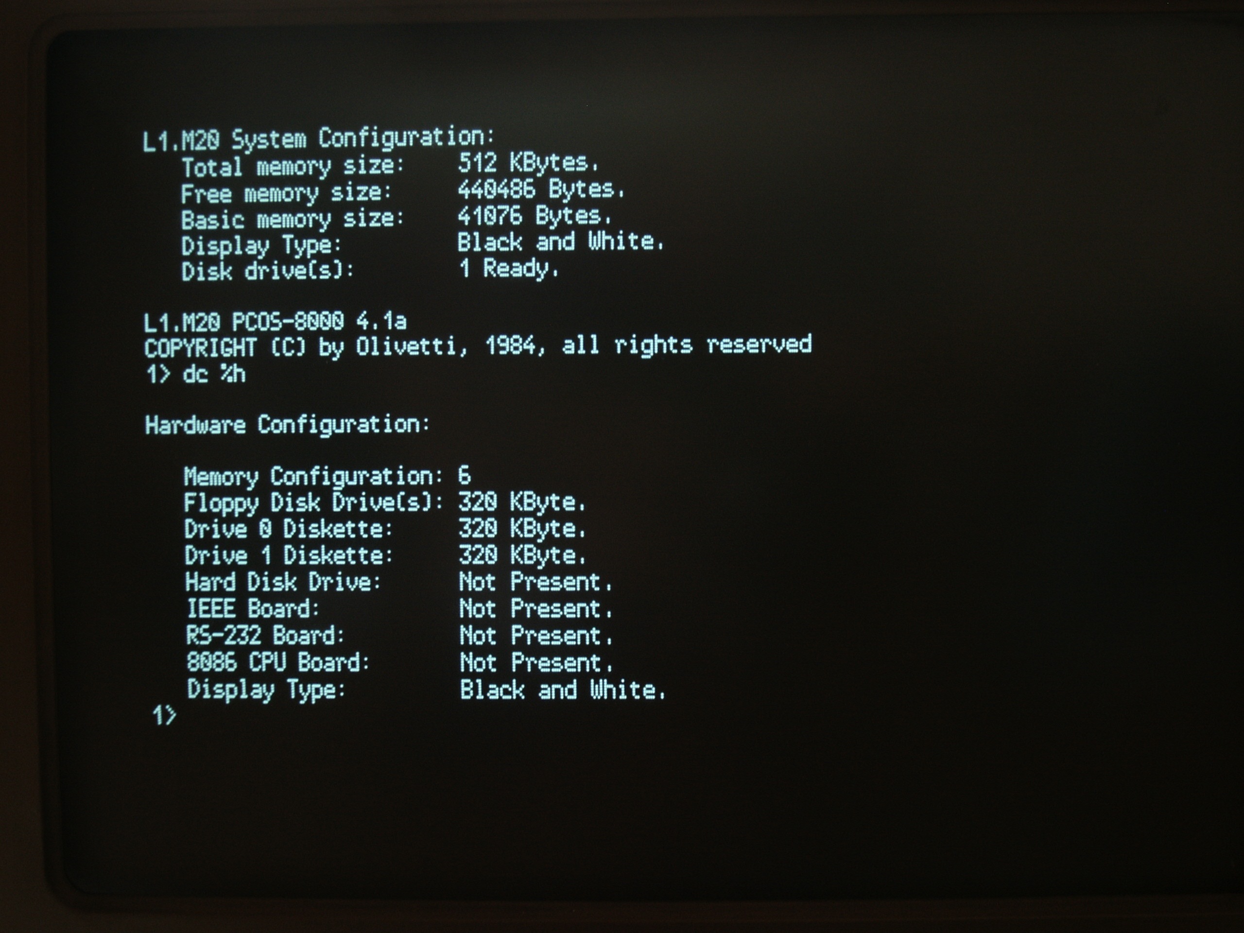
With the jumper settings suggested by Dwight, the BIOS at bootup tests for the presence of 128KiB memory expansions on the three slots and the system is configured automatically to the quantity of memory installed.
To allow an easy configuration of the system, I used a connector which allowed me to run the memory expansion without the signals from the other connectors. In this case, I can revert the circuit in a plain 128KiB expansion very quickly. In that case, I just have to disconnect cables coming from the two other connectors and rememeber that pin 3 and 5 of 74LS04 should not be left floating and must be tied to the ground.
With the jumper settings suggested by Dwight, the BIOS at bootup tests for the presence of 128KiB memory expansions on the three slots and the system is configured automatically to the quantity of memory installed.
Erratum
Dwight pointed out that there is an error on the schematics. Output at pin 3 and 6 of the 74LS00 should be connected to /CAS input of the SIMMs, ie pin 2 and NOT pin 27.
Other realizations
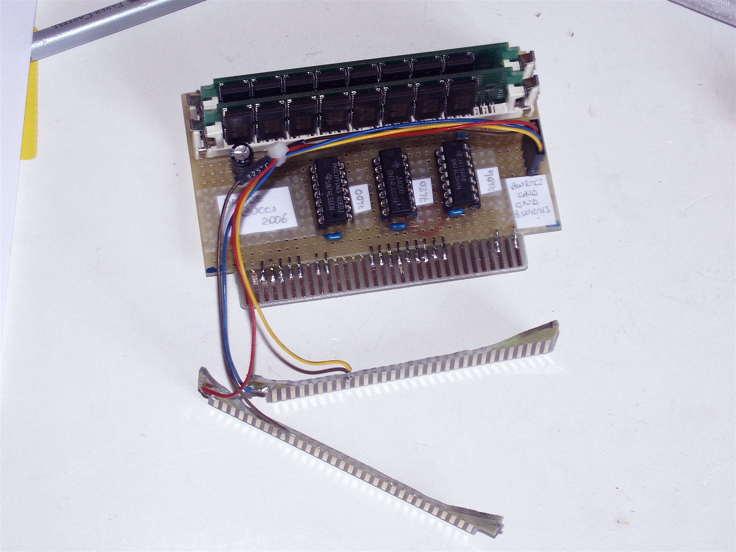 This is a photo of the expansion I made for Christian Groessler. It is pretty similar to the first realization.
 Christian's expansion mounted on a machine.
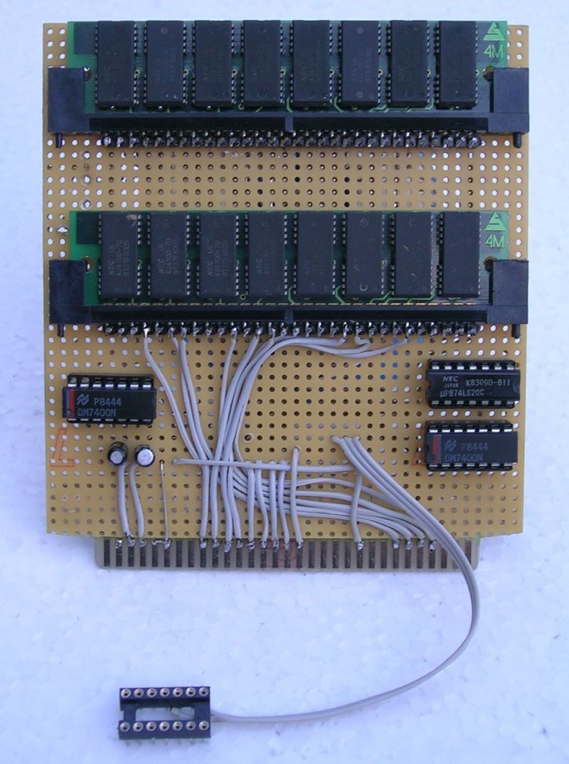 Andreas Senk has realized this expansion mounting vertically the two SIMMs and by seeking BWMCS2 and BWMCS3 signals not on the other RAM expansion connectors, but on the pins of the part generating them.
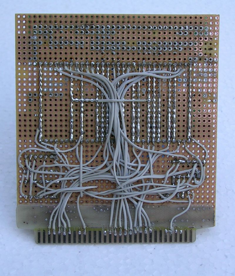 The back of Andreas' wirewrapped board.
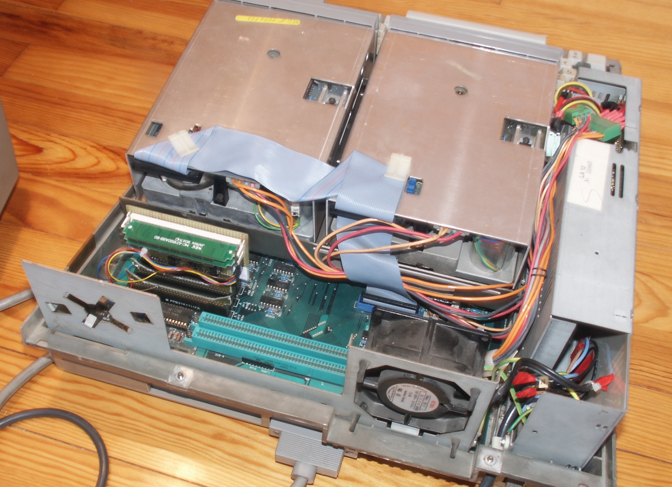
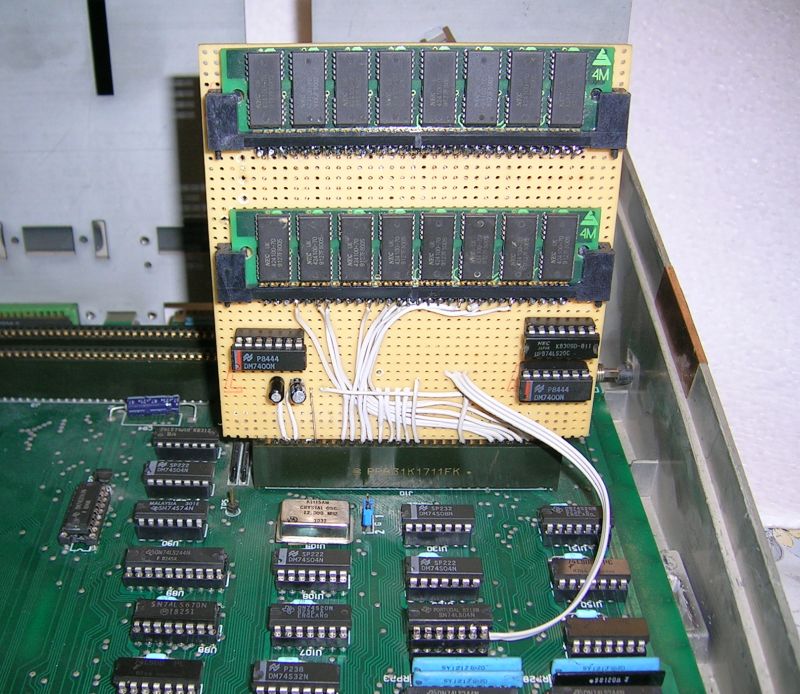 The 384KiB expansion installed on the system. You can see that the SIMMs mounted vertically allow to save space (expansion connectors are rather tightly spaced). Note the three BWMCS signals got directly from the part generating them.
Olivetti is a registered trademark of Telecom Italia. This site is not related to Olivetti nor to Telecom Italia. The material presented is meant for personal use only and is shared in a "fair use" spirit. If you own the copyright of some of the stuff presented here and you think it should be removed, please contact the webmaster.