
Building a 384KiB B/W memory expansion for the M20, part I
By Davide BucciGenesis
I had an unexpanded machine and I collected a little bit of software which needed more space in RAM than the canonical 128KiB. I was wondering how to expand my machine, when I come in touch with some other persons having the same will. In the site, the hardware description manual provides a lot of valuable information about the M20 organization, schematics and so on and I was quick interested in building an expansion on my own. Unfortunately, the schematics in the manuals are pretty hard to read. Apparently, there was a sort of automatic system in Olivetti that was used, so that every signal has a name. This is pretty useful, but in the schematics components are put without a particular order on the sheet with wires running all around the schematic without being organized in buses or even basic structures. Another problem was that the schematics were probably drawn by hand, with a lot of errors in them...
In this first part, we will see how to obtain a 128KiB memory expansion, in the second part, we will discuss about the possibility to expand this value up to 384KiB, in order to obtain a 512KiB memory on the M20.
I found in the manual the schematics of the 128KiB memory expansion which was used on the M20 in 1983. To understand the behavior, I copied the schematics with more human readable conventions in this page. It appears that the schematics of a 128KiB black and white Olivetti memory expansion was basically made by an array of 16 4164 chips, capable of 128KiB of RAM, with two NAND logic functions and a certain number of inverters, mainly used to buffer the signal.
I was a little bit intrigued by the fact that using a 4164 dynamic memory chip is not very different from using a more recent 30pin SIMM. Using a SIMM has a number of advantages. One of the most relevant, especially if you are using the old fashioned wire-wrapping technique is that is far easier to wire 30 pins than to wire 16 separate chips. Also, this was a good way to use two of the 30 pin SIMMs I collected. They are rather old now, but it is still common to find old computers given away for a few bucks which use them, so they are still today easy to find. The only issue is that you can find easily 1MiB SIMMs, on which you use only the first 128KiB.
I realized also that the bunch of inverters used as buffers in the original design can be left out, and indeed Olivetti removed part of them in later versions of the expansion (this is evident from photos you can find on this site and on the net).
The schematics and realization
Adapting the original Olivetti schematics to use 30 pin SIMMs is pretty simple.
The Olivetti M20 memory bus is composed by 16 bits, with separate signals for the lower and upper byte. This means that two 30 pins SIMMs should be used, each one providing 8 data bits. You find 8 address bits on the 62 pins connector which is provided on the M20 motherboard to hold memory expansions. The addressing technique is the classic ROW:COLUMN, which are multiplexed and strobed individually with the CAS and RAS lines on the bus, available for the lower and upper byte of the 16 bits.
The expansion can thus hold a maximum of 128KiB on each slot, selected individually by the BWRMC signal.
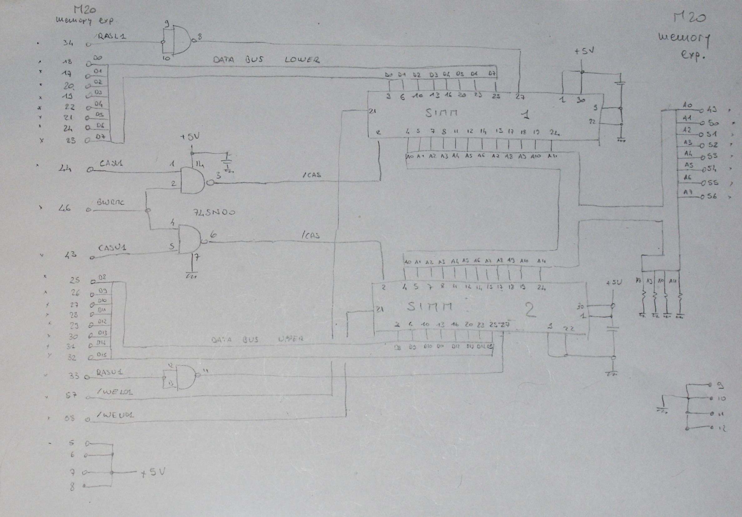
The expansion schematics is rather simple. There is a simple correspondence between the data and address buses of the memory expansion connector and the SIMMs. The only additional components needed are a single 74HL00 quadruple NAND IC, whose an half is used to select the SIMMs and the other one is used as a double inverter to change the sign of the RAS signals.
I mounted the expansion on a breadboard, using a connector from an old 8 bit ISA card. It appears that this standard share with the M20 the same number of pins (62). The connector was held in place by soldering several relatively high gauge wires corresponding to the alimentation connections. In my case, this provided a rather stiff mechanical connection with the board, but if in doubt, you can use epoxy glue to secure the connector to the breadboard. A valuable alternative can be the use of an ISA prototype card, but I found it is difficult to find now in Europe, at least in my local electronics shops.
The SIMMs support was taken from an old motherboard and can hold a couple of memories in place. The capacitor used in the circuit are useful to avoid spikes on the power supply lines and can be any value between 100nF and 1uF polyester.
Board configuration
The Olivetti M20 was able to handle both 32kBi expansions as well as 128kB ones. The different configurations were selected with the configuration of the jumpers on the mainboard. Dwight Elvey indications were of great help and I were able to correctly configure my M20 system for the additional memory. The description and photos of the jumper configuration can be found at this page.
Related pictures
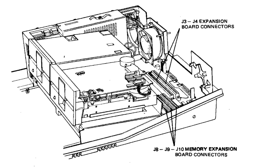 The position of the three memory expansion connectors. They are 31x2 pins edge connectors (with a pitch of 100 mils, i.e. 2.54 mm). The pin numbered 1 is the first toward the center of the motherboard, on the floppy disk side. It should be noted on the silkscreen.
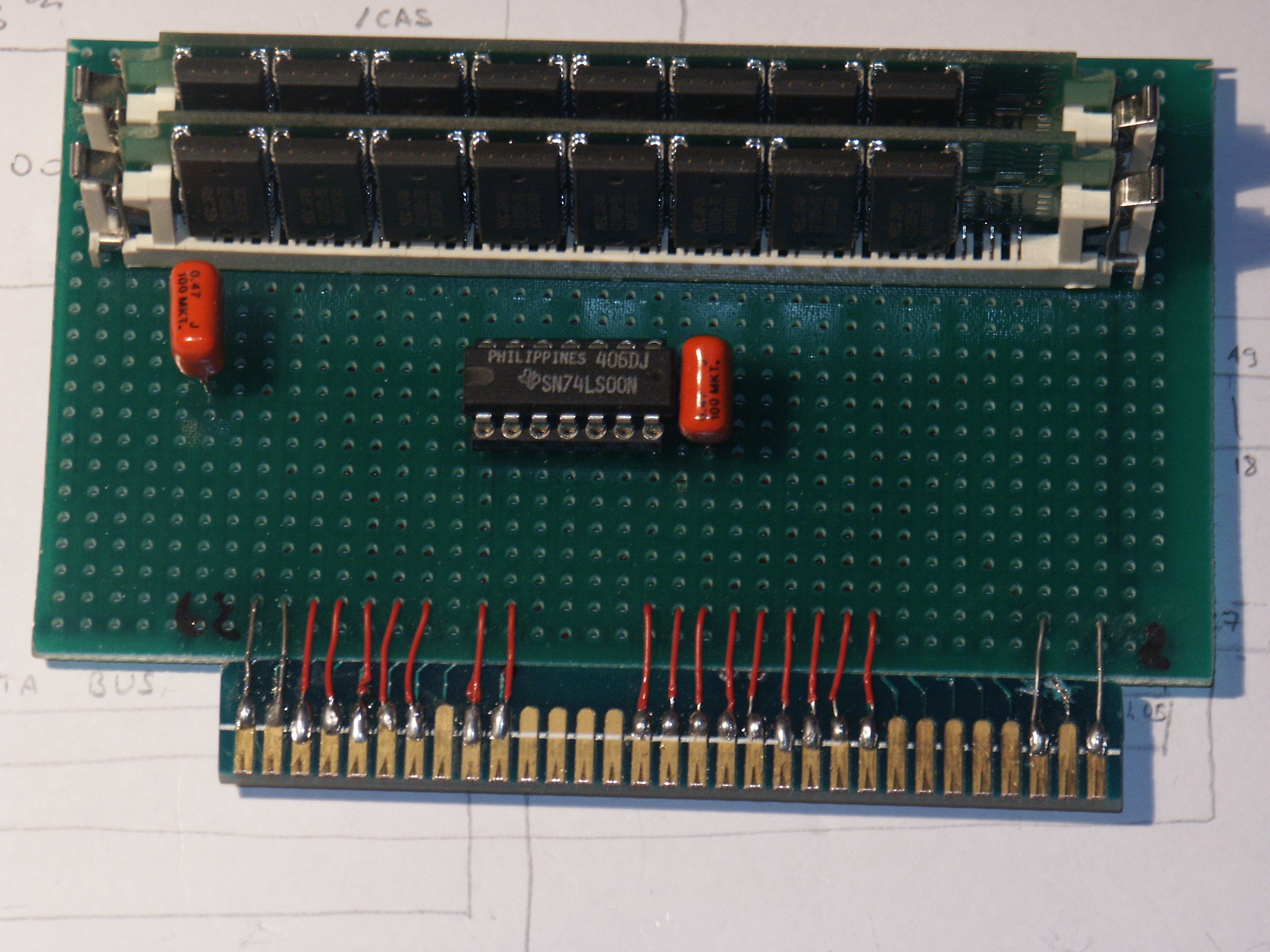 The 128kBi expansion mounted on an universal board. The connector was adapted from an old 8 bit PC ISA card.
 The back of the expansion. 16 data bits plus the address bus begins to need a little bit of connections.
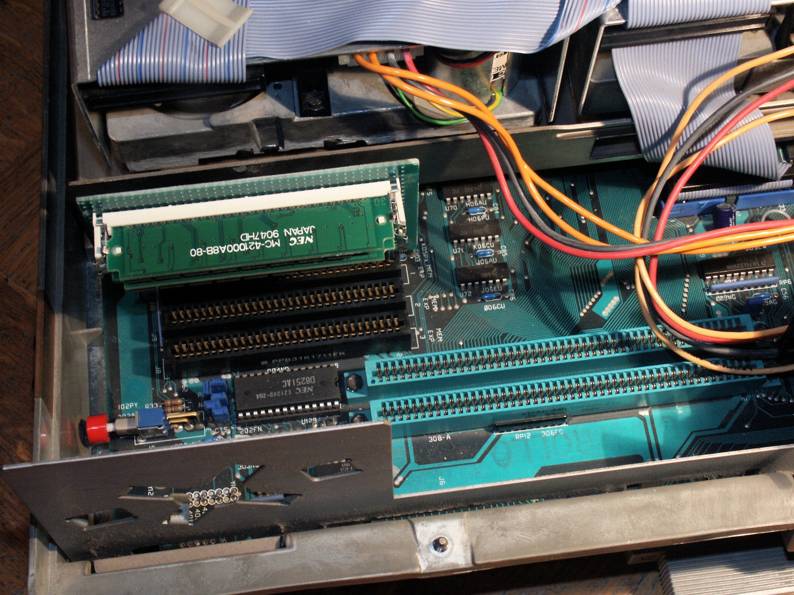 The expansion mounted on the system. There are not so many (yet!) M20s which can mount SIMMs memory like in this case. Be careful in orienting the board. Also, the two SIMMs take a lot of place and this means that the remaining slots should be kept unused or occupied with low-profile cards.
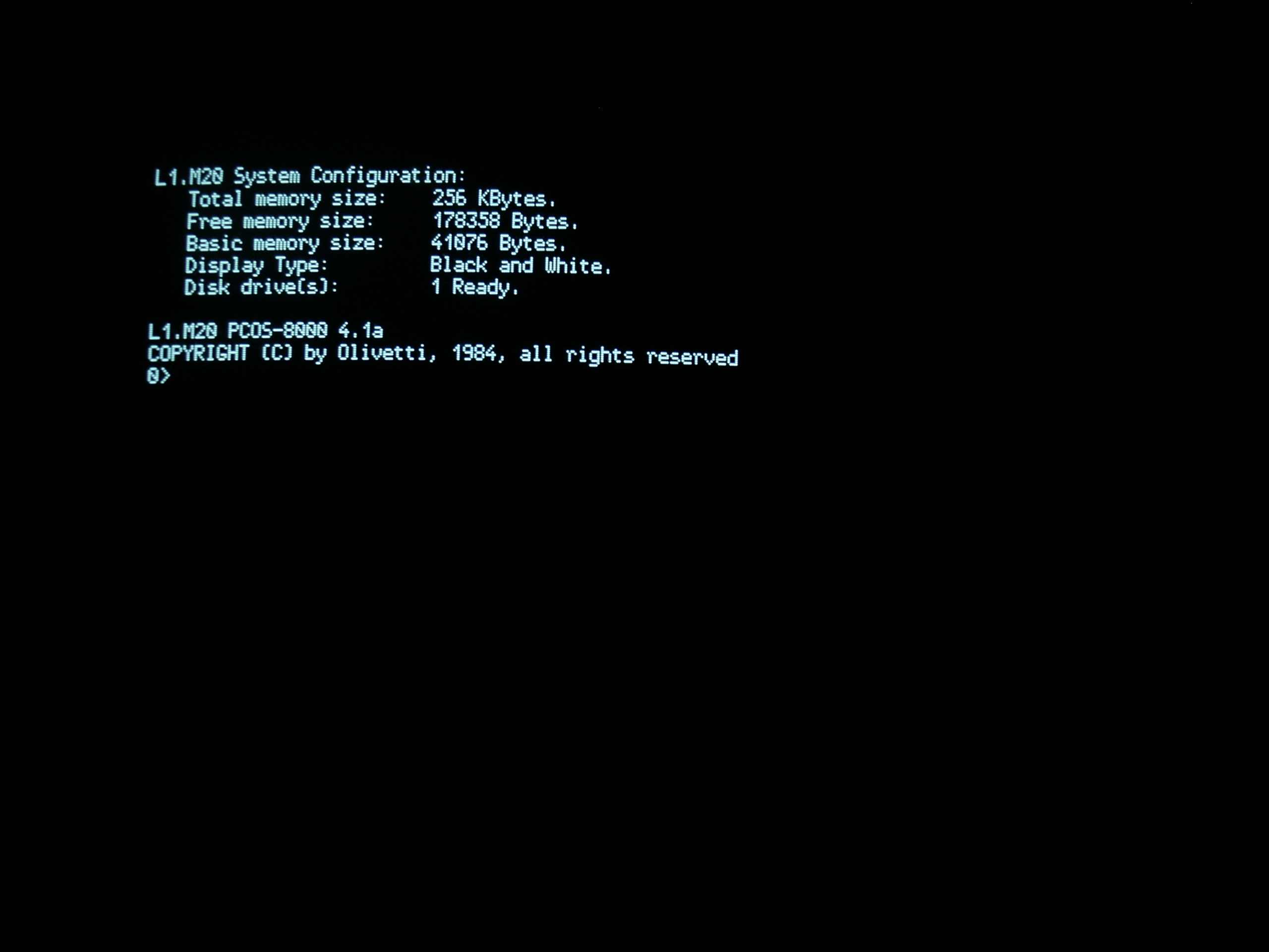 Now, I can boot the PCOS 4.1 with 256kBi of RAM.
Yes, but...
An interesting observation is that in our expansion we waste a lot of RAM space. For example, if we have two 1MBi SIMMs, we have only the 12.5% used in the expansion. Indeed, the main problem is that the address bus wires on the expansion connector can only address 128KiB. A solution can be the use of the other connectors, in order to better use our memories. Anyway, the total system memory which can be addressed is limited to 512KiB, even if in theory the Z8001 could address 8MiB. It is possible to use signals from the two remaining expansion connectors, in order to boost to 384KiB the amount of total memory expansion see by the system. This possibility will be explained in the second part of this discussion
Page log
- December 24, 2022 - Added the page log, correction of typos.
- July 1, 2006 - Page creation.
Olivetti is a registered trademark of Telecom Italia. This site is not related to Olivetti nor to Telecom Italia. The material presented is meant for personal use only and is shared in a "fair use" spirit. If you own the copyright of some of the stuff presented here and you think it should be removed, please contact the webmaster.